Answer the questions 1 through 15 in this writeup before coming to the lab. They will be collected at the beginning of the lab. Read the sections of the text referenced here, if you haven't already.
The Johnson noise voltage ``spectral density'' that appears across a resistor is en = [Ö(4kBTR)]. (See sections 7.11-7.14; pp 430-443 in Horowitz-Hill 2nd edition.) For a 1M resistor at room temperature (300 K) en = 1.3 ×10⁻⁷ V/[ÖHz], or ~ 4 mV rms in a 1 KHz bandwidth. We will, therefore, need a high gain amplifier whose intrinsic noise is small so that it does not cover up the thermal noise from the resistor.
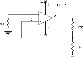
For the first amplifier stage, start near the left edge of the upper breadboard block (to the left of your tuned amplifier) and wire the following circuit:

Clip the component leads short and bend them so the component bodies lie flat against the breadboard - this minimizes stray capacitances. Use a single bus on the socket for all the grounds (probably the inner strip below the op-amp). It is a good idea to put 0.1 mF capacitors from the +15 V and the -15 V supply pins of each op-amp to ground to bypass the power supply.
The LF357 is an inexpensive op-amp with JFET input transistors and reasonably low noise. Use information from the spec sheet to find the following.
Since we will use the DVM to measure an rms voltage, vrms, we need to define a bandwidth so that this voltage can be predicted from the Johnson noise spectral density, en.
Now refer to your previous laboratory (Operational Amplifiers) and consider the three stage tuned amplifier that you previously constructed on the right side of the top block of the breadboard.
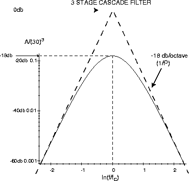
The use of the three stages results in a better definition of the bandwidth and reduces the gain at 60 Hz ( << f°) to the point where we have some hope of operating a completely unshielded high gain circuit like this in the presence of the large line-frequency fields in the laboratory. The overall gain is sketched below:

[Power levels, such as 30 watt or 40 watt, are often compared by taking the logarithm of the ratio of the Power levels. When comparing two power levels Pa and Pb, we might generate
n = log10([(Pa)/( Pb)])
and say the ``Power difference is n bels''. More usually, we generate
m = 10.0 log10([(Pa)/( Pb)])
and we say the ``Power difference is m decibels'' or ``a is m db above b''. When comparing voltages, across identical resistors R, then the ratio of the powers in the resistors is related to the ratio of the voltages.
m = 10.0 log10([(Pa)/( Pb)]) = 10.0 log10([(V2a/R)/( V2b/R)]) = 20.0 log10([(Va)/( Vb)])For example, if the voltage Va at a is twice the voltage Vb at b, then
m = 20.0 log10(2/1) = 20.0×(0.3010) = 6.02
and we say that ``the voltage at a is 6 decibels or 6 db above the voltage at b''. Note that this applies only if the two systems have the same impedance to ground. Perhaps both signals are moving in 50 ohm transmission lines.One can compare voltage gains in the same way as comparing voltages. For example, if a voltage gain is increased two-fold, then it has been raised by 6 db.]
Now we need to calculate the rms output voltage we expect for a given voltage spectral density at the input. We will assume ``white noise'', where the spectral density, en is independent of frequency. The rms input voltage in a bandwidth df at any frequency f is then en [Ödf], and the output voltage is A(f)en[Ödf] . We must add these voltages for all frequencies where we have any gain, but since the phases are random and independent, we must add their squares:
|
|
|
|
The peak gain of the tuned stages is quite sensitive to the exact values of the capacitors. If you want accurate results, it would be a good idea to remeasure the net gain of the three tuned stages at the frequency where it is maximum, and scale your calculated k to the extent that the measure value differs from 303/8. To do this, we use a sine wave from the signal generator as a source, inserting the ¸100 and ¸10 attenuators in order to set to a sufficiently low voltage. It is best to use your scope to measure the input and output voltages.
Just to check the noise contribution from the 741 stages, temporarily ground the input of the first tuned stage (make sure it is disconnected from the low-impedance LM357 stage output!!) and measure the rms output voltage of the last stage with the DVM - record your values.
Now connect the first tuned stage input to the output of the LM357. Temporarily short the 1M resistor to ground the input. Measure the output voltage. Subtract the contribution from the 741 stages (in quadrature) to get the noise due to the 357 stage only.
Is the correction significant? Use the result of Ques. 14 to convert your rms voltage to a spectral density at the input. How well does this agree with en from the data sheet?
Now remove the short from the resistor and again measure the output voltage. You can subtract the total (input shorted) amplifier noise. Is the correction significant? This does not correct for the amplifier current noise, - (Why not?) - but the current noise is unlikely to be significant for Rin = 1M or less. Convert this to en for the resistor. How does it compare to [Ö4kTR]? (300 K is close enough to room temperature.)
Be sure to look at the output on the scope as well as on the DVM. It should look like random noise. If it doesn't seem right, check with the instructor.
Get a 200 K metal film resistor mounted on a short shielded tube (from the instructor, if it is not on your bench!) and substitute it for the 1M resistor. Which side of the resistor should be connected to ground? What value do you get for en noise? Does it scale as you expect with R?
The resistance of metal alloys, such as the nichrome film in these resistors, is essentially independent of temperature at room temperature and below. We can therefore cool the resistor and check the expected T dependence of Johnson noise. Nest two Styrofoam coffee cups and fill the inner one with liquid nitrogen (LN2, T = 77 K) from the dewar in the lab. Don't spill it in your shoes! (If you have never handled LN2 before, you may want to ask the instructor to do it for you!) Immerse ~ 2 cm of the end of the tube in the LN2. (The resistance of a carbon composition resistor would almost double, if you used one here.)
After things settle down, check the scope to see it the ``popcorn'' due to mechanical contraction in the resistor has pretty much stopped. When it has, take a reading from the DVM and calculate en. Don't forget to correct for amplifier noise - it's starting to get important at these low levels.)
Note: save your breadboard in the cabinet again - you will use it for the Phase Detector Lab next week.
You will use your 3-stage tuned amplifier and low-noise input stage from the Johnson Noise lab. Construct the following circuit on the lower breadboard block as far to the right as possible (to keep it away from the 357 input). Be sure the square wave input comes in from the right side of the breadboard. (You should not be using either of the BNC connectors on the left.)
(You can use any one of the six devices on the 7404 chip. Note that it requires connections to ground and to Vcc = 5 V. Note also that the HI-300 requires a ground connection for input reference control. )

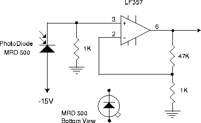
Set the pulse generator to give a 0-4V square wave output at a frequency near f°. Replace the resistor at the amplifier input with a 1 K and add a photodiode as shown below:

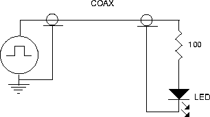
Put a ~ 25 mm piece of black tubing over the end or your photodiode to limit the amount of background light that strikes it. Bend the leads so it is aimed nearly horizontally of the left end of your breadboard, trying to point it a a part of the room that is not too bright (set up a dark screen, if necessary). Put a red LED in series with a 100 ohm resistor at the end of a coax cable and connect it also to the pulse output.

Now replace the 1K resistor with a 1M resistor and remove the LED. This will increase the light sensitivity by a factor of 1000. Looking at the amplifier output on the scope, you will see the Johnson noise of the 1M resistor, plus some 60 Hz hash from the room lights. If the output is saturating at any time due to pick-up, try placing a small piece (5 cm × 5 cm) of grounded Aluminum foil in such a way as to shield the input circuit. Check the output of the LM357 stage with the DC-coupled scope to be sure that it isn't saturating from ambient light. Set up shields or aim the tubing as necessary to keep the output of the amplifier last stage from saturating. Bring the LED near the end of the photodiode tube, while looking at the amplifier output (or point A). Note the high sensitivity - but also the large amount of noise. Now look at the filter output (point B) on the other scope channel.